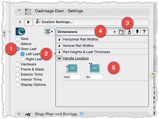
Its easy to choose the Door Handle style from the pullout list, but the actual position of the Handle is not in the same tab, just go to Door Leaf > Left Dimensions or Door Leaf , click the Style button and select the Dimension
Its easy to choose the Door Handle style from the pullout list, but the actual position of the Handle is not in the same tab, just go to Door Leaf > Left Dimensions or Door Leaf , click the Style button and select the Dimension
If you want to have a nice 3D model of a reeded decking panels remember that you can use the Reeded option from the Cadimage Slab Covering tool

Results

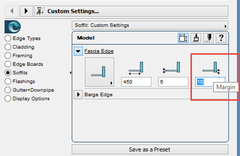
The Cadimage Roof Coverings tool now has the option to edit the position of the Fascia Edge in the settings
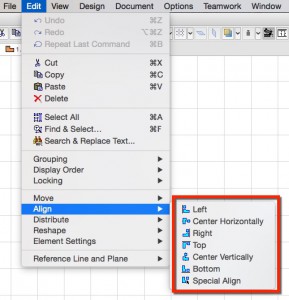
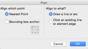
Want to align objects, text or drawings on your layout sheets?
Edit > Align allows you to align selected elements with each other.
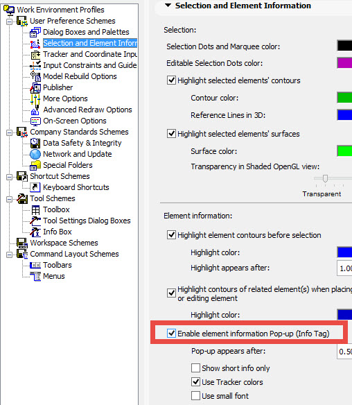
When you hover the cursor over most elements in ARCHICAD, an Info Tag pops up automatically displaying the basic information.
This is very helpful specially when Picking Up parameters or trying to select elements.
Although this function is enabled in the default settings, you may find that a custom Work Environment may have turned it off.
So go to the menu Options>Work Environment> Selection and Element information and enable it again.
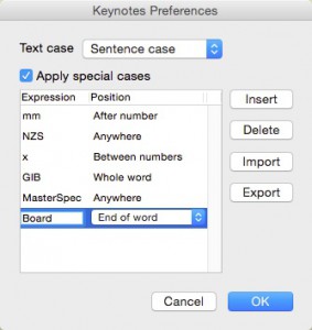
With the latest Keynote update before Christmas 2015 it include a new feature.
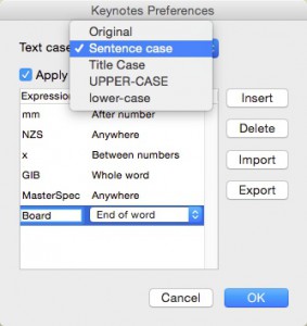
The feature allows the user to set the case for the title and description of keynotes (as a preference) and to specify exceptions, e.g. all upper-case except for the letters ‘mm’ following a number (so dimensions come out as 100mm rather than 100MM).
Sets these preferences using a new menu item Cadimage > Keynotes > Preferences
For more info on how to use the new feature, head over to the Cadimage Knowledge Base. https://cadimage.zendesk.com/hc/en-us/articles/207356153
new preferences dialog below.
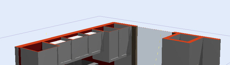
If you want to display the elements cut in 3D with a specific surface go to the menu
View>Elements in 3D view>Filter and Cut Elements in 3D…>
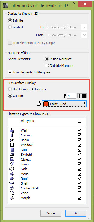
Or you can just use the element attribute.
Another way to go to those settings would be to click the drop down arrow symbol for the 3D Cutaway
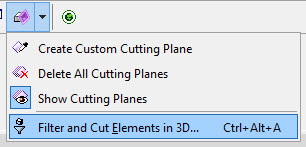
or use the following shortcuts to open the palette settings:
Ctrl+Alt+A for Windows
Option+Command+A for Mac
Now you can customize the display of the cut surfaces
Want to give your client that extra WOW factor?
Send them a GRAPHISOFT BIMx model which they’ll navigate through your 3D model on their computer.
The BIMx file then can be sent to anyone, and viewed with the BIMx Desktop Viewer.
For more information about BIMx, BIMx Hyper Models and even BIMx on your iOS and Android Devices see the links below.
http://archicad.co.nz/other-products/graphisoft-products/bimx
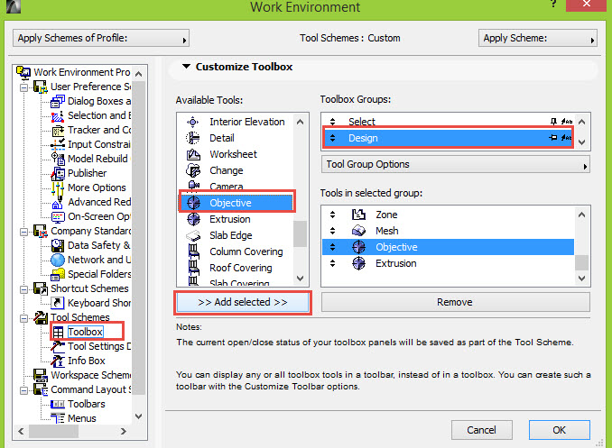
To have uniformity in our tools, the formely known Framing tool has been renamed to Objective in the Toolbox, this change affect only the ArchiCAD 18 and 19 versions
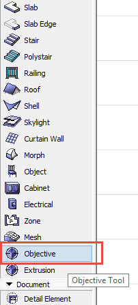
Remember that you can always right click the Toolbox and go to the settings to add the icon directly to your Toolbox.
Remember when you use the General Light Sources lamps in ArchiCAD you can always activate the effects.
One important effect is to display a visible light beam.

Using Spot Lights on a stage.

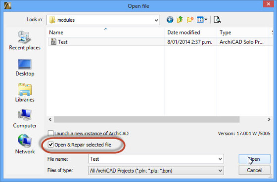
Do you have a corrupt file?
The new Open & Repair function is available in the Open dialogue. This function can fix v17, 18 & 19 damaged pln files in certain cases.
Introduced with ARCHICAD 17 a feature that will enable you to repair a corrupt file.
Just go to File>open>open> enable the box ‘Open and repair’ , finally select the file and click Open
If you make a change in a surface either in CineRender or Internal Engine.
It would be a good idea to match these settings so the surfaces look similar in your 3D view and your render image.
If you wish to do it so, just click the Match Settings button in the CineRender engine view.
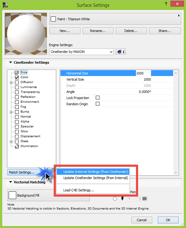
When matching the Internal Settings from CineRender, you can expect that the matched results in Internal Engine will only display the main colours of the surface, but not the actual texture created in CineRender.
For this reason it’s recommended that you can create a jpg image that could be added to the Internal Engine if you think it’s necessary. Generaly it’s not relevant how the display of the 3D window is because the render image is the important one.
Lately we noticed that many ArchiCAD files we receive display a missing Add-Ons dialog box at opening.
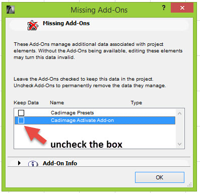
The dialog box means that the file has been migrated from an old version to a newer, likely from ArchiCAD 17 or older.
The Cadimage Presets, Activate Add On, and Core Components are obsolete Add ons that are no longer required when the file is migrated.
If you see a similar message in ArchiCAD 18 or 19, just uncheck the dialog box of the missing add ons, if you save the file, the next time you try to open if the dialog box won’t appear again.
If you are using the new Schedules Notes tool for Doors and Windows you will know that entering the data gives you 1.5 seconds between one character and the next one to type a description.
This is a setting in ArchiCAD that affects other settings like Doors and Windows, widths and heights, etc.
If you wish to have more time to type the descriptions of Notes in the Schedule Notes tool before the text updates itself, you can change the Dialog box delay settings:
There is a setting> Dialog Box Auto Rebuild Delay.

If you search a plan object from Cadimage in BIMComponents you may need to add the attributes for the plants to your project to display the surfaces correctly.
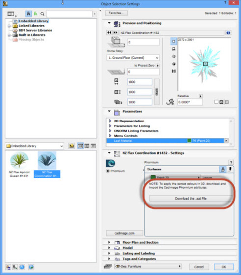
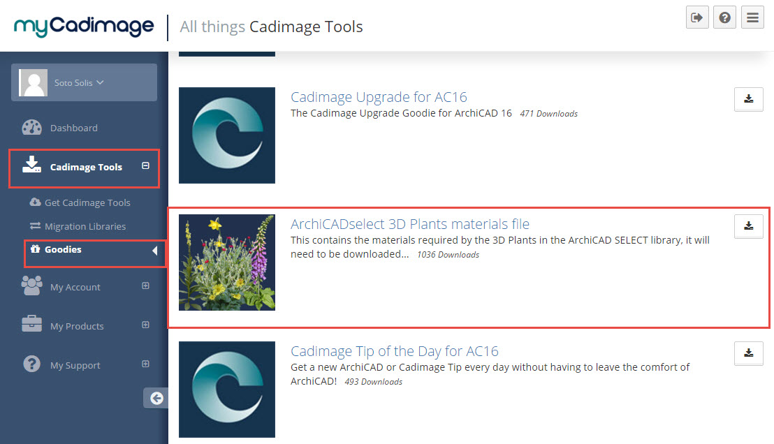
To enable the attributes in your file you can download the attributes file (Phormium Materials) from :
https://www.mycadimage.com/
Then go to Cadimage Tools>Goodies
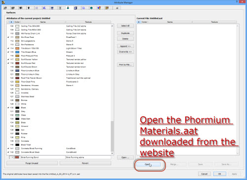
1. Then open the attribute manager> surfaces.
2. Open the file
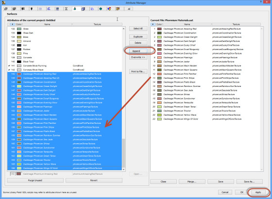
3. Select the attributes and click << Append
4. Apply the changes and click Create.
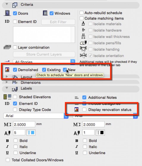
With a recent update to the Door + Window tool a new feature was added to the D&W Schedule.
Doors Windows Schedules Now Support Renovation Status
Getting Started with D + W Schedule
If you are using the roof covering tool and you wish to edit the position of the cladding origin, just click in the center editing node and offset it:
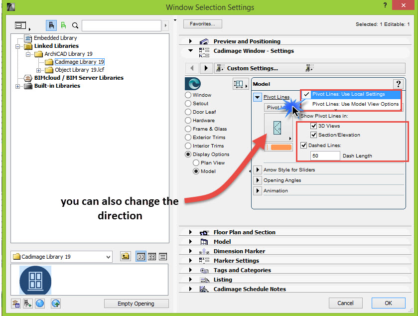
To display the pivot lines for Cadimage Doors or Windows you have two options

You can control them by the MVO, go to Document>Set Model View>Model View Options>Miscellaneous Settings for Library parts > Show Opening Lines in 3D projections

Or you can edit the settings to be independent from the Model View Options, go to the Door or Window settings
Display Options>Model>Pivot Lines

If you are using the Cadimage Door tool and wish to edit the position of a Sliding door, or pocket door opening direction arrow just go to
Settings>Display Options>Plan View> Arrow Styles.

If you have activated the Cover Fills on a Slab, you may want to display or not the fills in different stories.
In order to achieve that, so to the Slab settings to the Floor Plan Display settings and change it to Custom